User:ConsciousCode/sandbox
Audience: People with a passing knowledge of circuitry (resistors / capacitors) how to connect test probes, soldering a bonus. Anyone who knows and especially owns an Arduino should be able to follow this
Physical access is root access
— Security Operations
Hardware hacking means modifying existing electronics to use them in a way they were not intended to be used. Normally this means hacking in order to gain privilege escalation and compromise security, but it's equally applicable to eg unlocking the capabilities of a DVD player to act as a file server for backups. The complexity of a hack depends primarily on the intended market of the device. Usually the cheaper and simpler something is, the less they bothered to remove extra debug and ICSP (In-Circuit Serial Programming) hardware before sending it to market. Smartphones have an extreme level of complexity and cost so they tend to be on the higher end of being locked down and require a lot of research if it's even possible for a hobbyist. On the other hand, devices which don't have any significant level of miniaturization tend to still have all the knobs and levers the developers used to create the hardware in the first place.
Terminology
- Ground
- A reference to 0 voltage which determines the voltage of the rest of the circuit.
- Vcc
- Nominal voltage of the circuit, usually 5V or 3.3V.
- Header
- Through-hole or surface-mount exposed copper pads which can have pins soldered into them for easy access
- Line/wire
- A data signal for a particular protocol.
- Bus
- One or more lines implementing a protocol.
- Half-duplex
- A bidirectional line where data is transmitted in exactly one direction at any given time.
- Full-duplex
- A two-wire bidirectional bus where each line transmits in only one direction, so data can be flowing in both directions simultaneously.
- Baud rate
- The number of bits sent per second.
- Serial / Parallel
- A line which communicates one bit at a time, rather than a parallel line where eg 8 bits of a byte are sent across 8 wires simultaneously.
- Synchronous / Asynchronous
- A bus is synchronous if it has a clock which synchronizes a line between a controller and peripheral. Otherwise it's asynchronous, and the baud rate is agreed on ahead of time.
- PHY
- A physical implementation of a protocol.
- In-band / out-of-band
- Data agreed upon within or outside the protocol.
- Active high/low
- The line is considered "on" or the 1 bit when the voltage is high/low. Active low sounds weird, but it's primarily used for alert signals because it can be implemented with a single transistor.
- Interrupt
- A line which alerts the controller that the peripheral has something to say.
- IC
- Integrated Circuit, small black squares with bits of metal (pins) on the sides which have all the hardware inside to perform a particular function. These include everything from voltage regulators to microcontrollers and external memory.
- PCB
- Printed Circuit Board
Tools
Most of what is needed for hardware hacking is adapters for translating low-level interfaces to USB so your computer can access them. The gold standard for interfacing is FTDI. When ordering them, Amazon will ship them within a few days for double or triple the price while AliExpress ships from China and may take a month. In order of utility,
- Single-Board Computers with these interfaces exposed
- Raspberry Pi Zero ($10)
- Multi-interface adapters (if you can't get an SBC)
- FT232H USB to JTAG/UART/SPI/I2C Module ($18 on Amazon, $6 on AliExpress)
- CH341A USB to UART/I2C/SPI ($9 on Amazon, $4 on Ali)
- Logic Analyzer ($13 on Amazon, $5 on Ali)
- These are not necessary, but can be invaluable for identifying unmarked headers
Single-interface adapters (especially for UART and i2c) are available, but not much cheaper than the multi-interface adapters.
Interfaces
RS-232
RS-232 (Recommended Standard 232) is an extremely old serial protocol from 1960 used for teletypewriter operator consoles and more rarely inter-chip communication. Nowadays it's more commonly referred to as U(S)ART (Universal Synchronous/Asynchronous Receiver/Transmitter) which is technically a PHY which is used to implement communication standards such as RS-232. Because UART isn't a communication standard per-se, it has a lot of variation in its interface.
At its most extreme, a UART-based interface can be a single wire half-duplex interface, where the peripheral and controller both have control over the bus and have to agree out-of-band which one should control the bus at any given time to avoid thrashing communication.
Usually a chip's UART will use two wires (Tx and Rx) to implement a full-duplex stripped down RS-232.
More rarely a chip will implement more RS-232 signals which you can connect to most USB adapters. They're almost never necessary because they communicate readiness to receive data, and even the cheapest microcontrollers are fast enough to always be available. If you ever need them, it's good to know that RS-232 calls the terminal that connects to a device "DTE" (Data Terminal Equipment) and the device itself "DCE" (Data Communications Equipment). This was from the dawn of computers when you had one big shared mainframe and dozens of "dumb terminals" which let you run commands and see their results.
SPI

SPI (Serial Peripheral Interface) is an old (1980s) communication protocol nowadays primarily used for EEPROM memory, which can be useful for hacking budget microcontrollers that don't have their memory integrated. Communication is toggled by enabling the Chip Select (CS) line.
In 2022, the OSHWA (Open Source HardWare Association) changed the acronyms used by SPI because of their tacit usage of slavery terminology. For at least a few more years one is likely to see both kinds in the wild, so both are listed here.
- MISO / POCI - Master In Slave Out / Peripheral Out Controller In
- MOSI / PICO - Master Out Slave In / Peripheral In Controller Out
- SS / CS - Slave Select / Chip Select, sometimes omitted if only one device is on the bus
- SDI / SDO - Serial Data In / Serial Data Out, can be either POCI or PICO depending on if the device is a controller or peripheral
- INT - Interrupt, relatively rare for SPI
SPI can be half-duplex using only one wire (plus Chip Select), but this is very rare. Communication is initiated by the controller, then it stays quiet while it waits for the peripheral's response.
Despite its name, SPI is not strictly serial. Variations exist for transmitting 2 (Dual SPI), 4 (Quad SPI or QSPI), and even 8 (OctoSPI) bits at a time. QSPI is actually used by most modern SD cards. For low-level hacking, only Single SPI is actually useful because the others are meant for high-bandwidth memory rather than eg program memory.
i2c
i2c (Inter-Integrated Chip) is an old (1980s) communication protocol which is used nowadays for peripheral control. Unlike SPI, it's packetized and toggled by 7 or 10 bit addresses. It's very useful for controlling peripherals directly when you can't get access to the microcontrollers.
- SDA - Serial DAta
- SCL - Serial CLock
- INT - INTerrupt, very common for i2c
JTAG
JTAG (Joint Test Action Group) is an old (1980s) synchronous factory test standard allowing boundary scanning and ICSP of daisy-chained chips. It uses no less than 5 signals, and often many more, but is very powerful if you can find it because it usually gives you complete and total access to every JTAG-enabled chip on the board.
- TDI - Test Data In
- TDO - Test Data Out
- TCK - Test ClocK
- TMS - Test Mode Select
- TRST - Test ReSeT (optional)
SWD
SWD (Serial Wire Debug) is a very new (2017) 2-wire variant of JTAG defined used by low pin count ICs. Unlike JTAG, it does not support daisy chaining and so the access it provides is limited to a single IC and interfaces which can be explicitly accessed via the JTAG registers. If you find an unlocked SWD interface, you're done. It gives you complete control over the system with only 2 wires, and is powerful enough to let you read and write registers and memory of the microcontroller while it's running.
- SWDIO - Serial Wire Data Input/Output
- SWCLK - Serial Wire CLocK
Other
More exotic interfaces exist, but their popularity and usefulness for initial hacking are much less than the above.
Header Hunting
Selection
When hardware hacking, the kind of device you try to hack can be very important. You want cheap, old, low-effort devices ideally owned by millions of people. If you don't have one in mind, thrift stores are an excellent source of these. Always keep in mind the capabilities of the device; you will never be able to turn a DVD player into a high performance computer, but you might be able to embed other devices into it to make it a multimedia center.
Unfortunately many devices with high hack-potential are also incredibly tightly locked and not even professional hackers have managed to get them to do anything except their intended function. This includes most smart phones, which are just too tightly engineered to have easy access points, but also products like Amazon Alexa have been found to be near unhackable, as cool as it would be to install your own custom assistant firmware.
Google it
As fun as it can be to figure out how to hack a device, there's a good chance someone else has already figured it out and they probably did it better than you can. Google the model number before you even open it, because you might find someone else determined it to be too much trouble to hack and you can save the effort.
Open it
Before anything else, unplug the device and maybe even let it rest 30 minutes.
Great care must be taken when opening any device, especially new ones, because the case may have hidden tabs you can accidentally break off or glue which requires enough force to break the case. It's usually possible to open a device without any damage or force. Look for screws, which may be under stickers or rubber feet, and stick flat objects into any grooves you see. Apply some force to see if it will give, but if you have to use too much you probably missed a fastener somewhere.
At each step of the disassembly, take a picture of what it looked like before so you know what it should look like after you put it back together. Take note of the size and shape of each screw as well, as they may differ and require some kind of organization to match them back to their original place. You don't have to be so thorough as to match each screw to exactly where it came from, just what sizes go with which locations.
Disassembly
Once the case is open, you'll see the guts of the device itself. This is the easy part of disassembly because at this point it's designed for serviceability. Keep taking pictures and unscrew every circuit board or component you can find until everything is in pieces. This lets you see all sides of the boards, any markings they might have, and any headers they might be hiding. Often devices will contain multiple boards connected by board-to-board wires like flat cables or JST connectors. You need to unplug them as needed, also taking note of how and where they connect to each other.
If you see a thick board with a lot of black tubes on it, this is probably the power supply unit and you should be very careful when handling it. They aren't dangerous on their own, but those big black tubes are called "capacitors". They're discrete components which store charge like batteries, but are optimized to release all their energy at once. Unscrew the PSU, then take your screw driver and touch the metal bits underneath the black tubes to discharge them. If they're thumb-sized or bigger, they may make a loud POP, and afterwards do nothing. Unless they're in a CRT TV they're probably not lethal, but it will hurt a lot if you touch them before discharging. Most products made after the 1980s will only have these massive capacitors on the PSU, and if they do have them on other boards they're probably there for their high capacitance (to eg filter audio signals) rather than their charge capacity.
Secrets
Most PCBs have what's called a "silkscreen", which is white or black ink drawn on the board to aid manufacturing and keep track of which components go where. Most of these will be "reference designators", an alphabetic prefix with a numerical suffix. This isn't super useful, but can aid in identifying what signals various wires carry. Some common reference designators include:
- R - Resistor, restricts the flow of voltage
- C - Capacitor, stores charge to suppress voltage ripples and filter signal frequencies
- L - Inductor, resists high frequencies
- D - Diode, only lets current flow in one direction
- Q - Transistor, a kind of electronic switch
- U - Integrated Circuit
- F - Fuse, literally breaks if too much current flows through it to protect from power surges
- H - Hardware eg screws
- J - Jack, some kind of connector to carry signals into or off of a PCB
- JP - Jumper, exposed copper pads close together which lets you connect two lines together, usually to set some semi-permanent configuration by the manufacturer
- S - Switch or button
- T - Transformer, usually used in power supplies to convert AC to DC
- TP - Test Point, exposed copper pads which give easy access to a signal line or power wires
- X(TAL) - Crystal oscillator
- H - Pin Header
There are hundreds more, and they aren't always what they normally mean. Reference designators are not a standard, they're maintained by convention alone.
Header Hunting =
The first things you should look for are headers. These stand out a lot. They're lots of big holes close together and covered in metal. Usually during development, these have header pins soldered into them so the developers can easily plug in their test equipment. Then when they go to market, they aren't removed because doing so would mess up circuit routing, require they be added back in if further revisions are done, and then there'd be no way to test hardware faults reported by customers. Because they're used for testing and development, they tend to give a lot of access to the hardware for little to no effort, though sometimes ICs are programmed to disable their debug capabilities. Rarely they'll even still have pins in them (to make flashing the firmware at the factory easier).
Once found, look for silkscreen text nearby which labels the pins
The ones you want to pay the most attention to are U, H, J, and JP (IC, Header, Jack, and Jumper) although it's also usually obvious what they are just by looking at them.
Examples
Monitor
<templatestyles src="Module:Gallery/styles.css"></templatestyles>
-
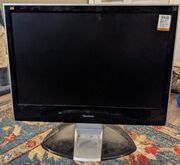
Cheap monitor from Goodwill I've had in my closet for 5 years
-
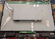
9 screws and a spudger behind the bezel
-
Remove the RF shield
-
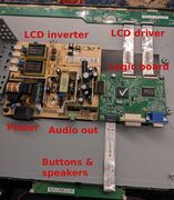
The logic board after getting rid of the QC checkmark with nail polish remover


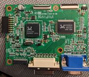
This is a more advanced example. There are no headers or relevant test pads, and the underside has nothing at all. However, the two Realtek ICs are clearly labeled and easy to find confidential datasheets for. The one to the left is RTD2120S, an embedded 8061 microcontroller designed for monitors, and the one to the right is RTD2553V, a TMDS/VGA decoder. This monitor must have been made before HDMI got big, because it has a DVI-I plug (mixed analog and digital) while HDMI uses identical signals and this chipset should easily support it. Interestingly there's a much smaller chip in the upper left which is labeled ATMEL640, a very valuable find. Atmel is generally extremely hobbyist-friendly due to its AVR ATmega and ATtiny product lines which Arduino is built on, however documentation for this chip is nonexistent. It may potentially be a knockoff chip, but a little sleuthing looking for its package type (TSSOP-8, a thin 8-pin surface-mount IC) suggests it's related to ATtiny45, Atmel's pinouts don't have much variation, and a quick glance at what the pins connect with matches. 3 of the GPIOs are unused and tied to ground, while another 3 seem to match SPI and go to the RT2120S.
According to the datasheet of the RT2120S, it supports ISP (In-System Programming) via the DDC lines of both the DVI and VGA DDC buses (Display Data Channel, standardized i2c at addresses 0x50 and 0x51 which give information about the supported display resolutions). Thus, we know how they programmed it in the factory, how to download the firmware for disassembly, and how to upload custom firmware. There's also an enormous amount of room we could shove a tiny computer into if needed. It also has dozens of GPIO which probably connect to the RTD2553V's parallel bus to give it commands and draw simple graphics which we could customize. H4X3D!
Degrees of complexity Prepopulated header with labels Unpopulated headers, maybe no labels Vcc/GND pins easiest to find Test points IC datasheets Software hacking